Related Documentation
MNS iS
1TGC910211 M0201 MNS iS Interface Manual MLink, Release 7.0
1TGC910111 M0201 MNS iS MLink Upgrade Kit Manual
1TGC910221 M0201 MNS iS Interface Manual Web Interface, Release 7.0
1TGC910241 M0201 MNS iS Interface Manual Profibus, Release 7.0
1TGC910251 M0201 MNS iS Interface Manual Modbus, Release 7.0
1TGC910291 M0201 MNS iS Interface Manual PROFINET IO, Release 7.0
1TGC910281 M0201 MNS iS MControl Interface Manual Profibus Direct, Release 7.0
1TGC910261 M0201 MNS iS Interface Manual Redundancy, Release 7.0
1TGC910271 M0201 MNS iS MConnect Interface Manual, Release 7.0
1TGC910001 B0204 MNS iS System Guide
1TGC910201 M0201 MNS iS Quick Guide Installation and System Setup, Release 7.0
1TGC910090 M0201 MNavigate Help file V7.0
1TGC910018 M0208 MNS iS ATEX – Enhancements for Safety
Related System Version
The content of this document is related to MNS iS System Release 7.0.
The described functions are designed but may not be fully implemented in all details. Please refer to the current system guides and release notes regarding possible restrictions.
Introduction
The system interface MLink is an industrial PC equipped with interface cards and ports required for communication internally to MControl and externally to process control systems.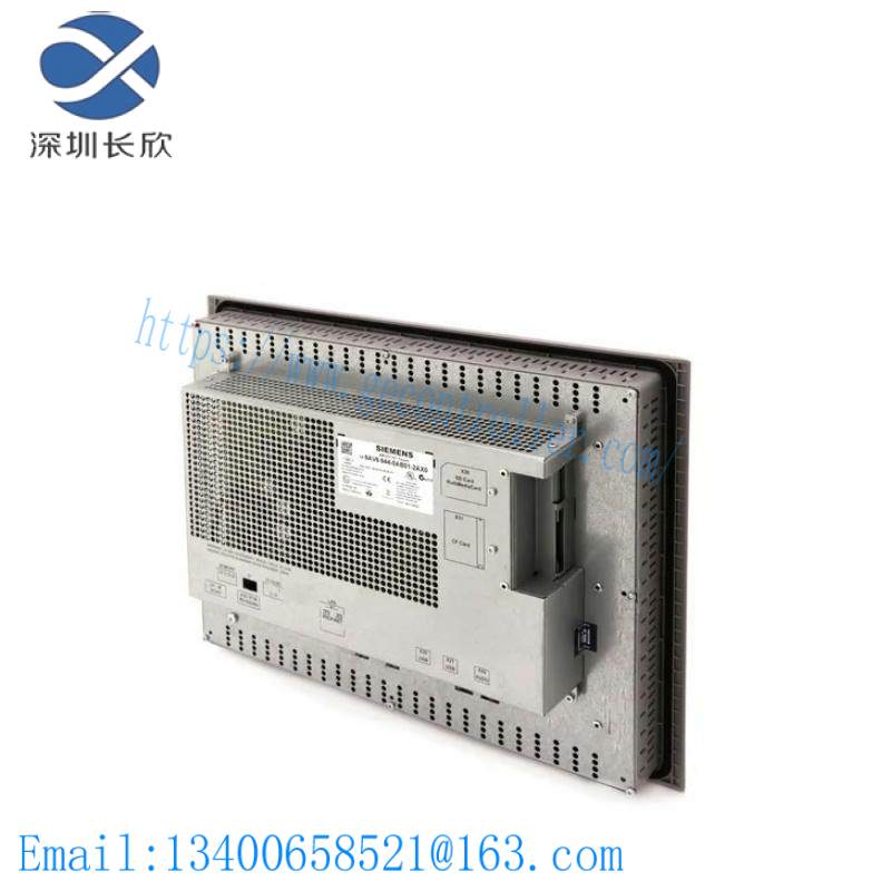
Figure 1 MLink
One MLink can communicate internally with up to 60 MControl. If more than 60 MControl are required, then additional MLinks have to be used.
Hardware Types and Technical Data
The configuration of MLink depends on the selected communication protocol to the DCS. Following communication interface protocols are available:
ROFIBUS DP (-V0) and PROFIBUS DP-V1
MODBUS RTU / TCP
PROFINET IO
System functions such as MLink web interface (MView), OPC connectivity and time stamp are possible with all MLink types.
For communication to MControl a dedicated interface plug (switchgear bus connector) has to be used dependent on system configuration (redundant, non redundant system).
Software Modules
MLink contains different software modules depending on its initial configuration. The software modules are available on request.
Following software modules are available:
Web Server
OPC Server (DA & AE)
Fieldbus
Time Synchronization
Redundant Operation
If a specific module is not available on the MLink, please contact your local ABB LVS Sales organization should this be required.
Web Server
A Web Server can be activated inside MLink. Through network connection web interface information can be displayed on MView or a PC using web browser software. For details about Web Interface see the document:
MNS iS Interface Manual Web Interface.
OPC Server
With MNS iS an OPC Server (DA & AE) is available. The software is typically installed on a server as part of the automation control system. The software installation program is delivered separately. If activated, the MLink functions as a data provider for the MNS iS OPC Server. For details about OPC Server see the document:
MNS iS Interface Manual OPC Server.
Fieldbus
MLink can include Fieldbus communication to DCS. The type of Fieldbus must be selected before ordering the MLink type. The Fieldbus specific information (PROFIBUS, MODBUS etc.) can be found in the following documents:
MNS iS Interface Manual Profibus
MNS iS Interface Manual Modbus
MNS iS Interface Manual Profinet IO
Communication Interface Connection
Switchgear Network (internal)
The internal communication between MLink and MControl is via the switchgear bus. The wiring is located within the MNS iS cubicle. The bus cable is connected to the blue Sub-D 9 terminal located on the front of the MLink at the upper part of the device. The internal communication does not require any configuration.
Switchgear Control Network
MLink can be connected to a standard 10/100 Base-T Ethernet network through LAN2 interface (Switchgear Control Network). Network components are standard (COTS – commercial of the shelf) components. No specific components are required connecting MLink to the network.
Examples of connections are shown in the following figures. Additional MLink and MNS iS tools (Engineering tool MNavigate, web interface, OPC Server, Time Server) are connected to this network (see Figure 2). The cable is CAT5, connector type is standard RJ45 type.
Option 1
If the MLink is directly connected to MView or a PC with web browser a cross-over network cable is used. On the MLink, the cable has to be connected to the right Ethernet connector (LAN2), on MView the cable has to be connected to the Ethernet connector. The cable type is CAT5 cable.
Option 2
MLink connected to Switchgear Control Network providing facility to connect additional MNS iS MLink and tools (e.g. OPC Server, PC with web browser for monitoring etc.). A network switch has to be installed in the plant. MLink and MView are connected to the switch with standard CAT5 patch cable.
Option 2 allows using fewer number of MView. However, all MLink connected to the same network can display their data on all MView connected to the same network.
Time Synchronization
In the MControl Alarms and Events can be provided with a time stamp. The time and date is received on MControl from MLink via the internal switchgear bus. In order to provide the correct time and date the Time Sync option must be activated in MLink and it may require a time server in the switchgear control network.
The protocol used for time synchronization is the standard network time protocol (NTP).
Related product recommendations:
XP POWER F7E1A6G2 10005836
Rockwell Automation A-B 802B-CPDBXSLC3802B
GE 36C774524AAG363PL
IXYS DSAI110-18F
Pro-Face PFXSP5B10 SP-5B10
ABB 64209396
Bently Nevada 3300/46
Rockwell Automation 700S-P220A1NEMA NEMA
A-B 6200V-DPDVI2
Kollmorgen TTBL 4207-B40614-0271
Bosch Rexroth R911289806
ABB DSQC653 3HAC025918-001
Baumuller BUS6-VC-AC-0069 AC
Panasonic MADDT1207L01
Siemens 7SJ5115-4CA02-2BA0
More…
Leave a comment
Your email address will not be published. Required fields are marked *